|
As of December 31, 2001, there has been no actual progress on the
layout. However, there is some work going on in preparation for getting
the CSXT Shenandoah Division V2.0 layout underway.
Very good progress has been made on the working drawings for the new layout.
The layout design has been essentially completed enough for me to feel
comfortable with starting benchwork very soon into 2002. There may still be
changes made to the design, but I feel comfortable with the overall
configuration of the layout and its ability to meet my design and operating
goals. Look for the plan to be posted in the Design
section of this web site in the near future.
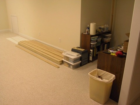
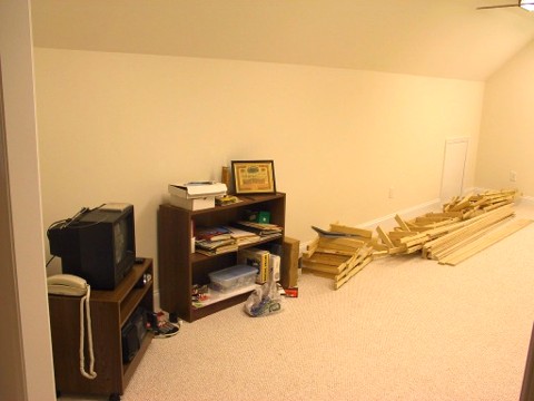
On November 4, 2001 and November 23, 2001, Cherie's dad came over and helped
cut 1 x 2 and 1 x 3 "lumber" from 4' x 8' sheets of birch plywood.
Even though I hadn't even started the upper-level design yet, we went ahead and
did this while the weather was warm and dry to have some "lumber" on
hand before starting the benchwork this winter.
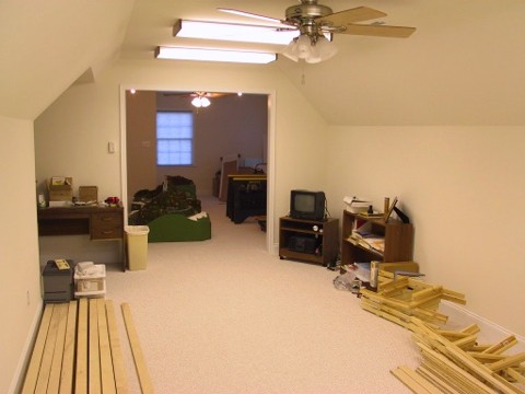
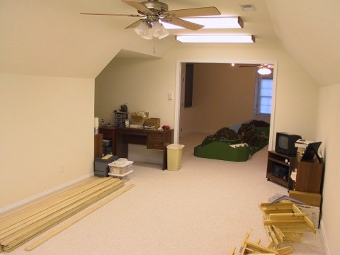
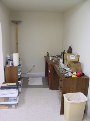
On December 22, 2001, my dad came over and helped me install the first 4 of 8
eventual fluorescent fixtures. The first 4 fixtures were installed in the
Salem/Covington/staging room. These are four tube fixtures that are four feet
long and give a dramatic improvement in the lighting conditions of the room.
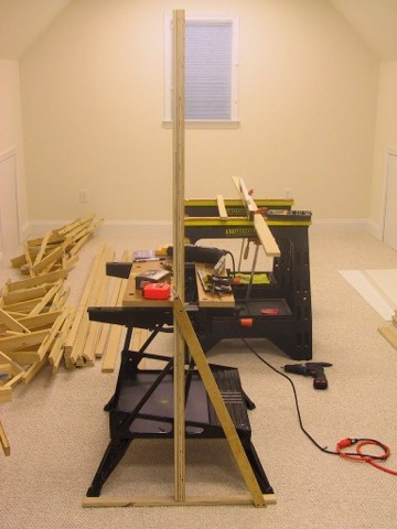
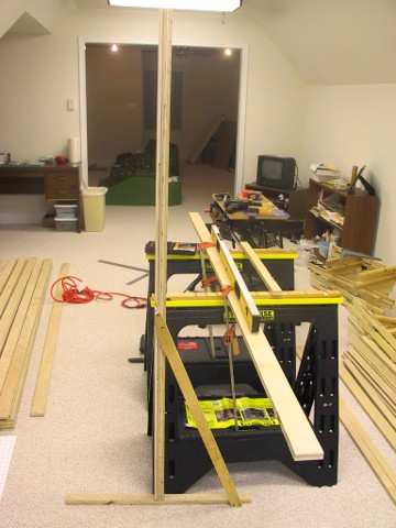
On December 24, 2001, I put together "the prototype" (as Norm
Abrams would say on The New Yankee Workshop) for the benchwork supporting
the two new long peninsulas as well as the shorter new peninsula. These
peninsulas all need to be freestanding but able to support the double-deck
layout. Chuck, Todd, and Jan came up with some good ideas on how to handle this
benchwork, and I think the resulting design will be fine. The wall which
supports Salem has studs on 24" centers, so I mocked up a piece of
3/4" birch plywood supported on 24" centers to see how much deflection
there will be. Overall, I think the more traditional 16"-18" centers
are better (maybe I'm being conservative), but I think the 24" centers will
be fine on that one wall.
Various portions of December 26-31, 2001 have been spent finalizing
some design changes to the upper level and drawing the actual benchwork
and supports. I have all of the lower-level benchwork drawn in 3rdPlanIt
for the Salem/South Salem/Wadesboro area. Next up will be the upper-level
benchwork for that same area. After that part of the benchwork is drawn,
I'll then finish drawing the benchwork for the other room. Being able to
see the benchwork in a 3-D view in 3rdPlanIt has me excited about starting
the layout. 3rdPlanIt will allow me to calculate the amount of lumber
needed for the benchwork (as well has how many turnouts and how much
flextrack).
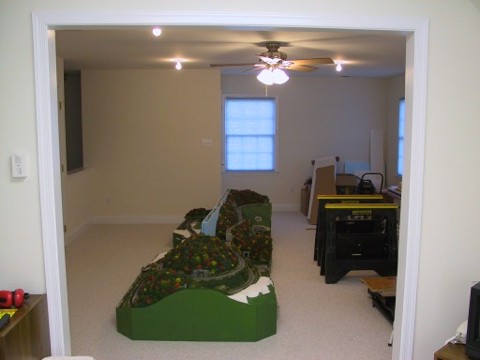
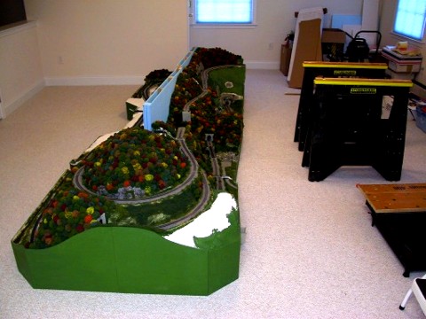
I've included some photos below of the new fluorescent fixtures, the New
Castle peninsula, and the new benchwork support prototype. The details of the
prototype for the benchwork support are discussed in the caption below its
picture.
|